
How to Set Up RC Car Radio for Reliable Control
Learn how to set up your RC car radio, bind transmitter and receiver, choose batteries, and troubleshoot signal issues for reliable control.
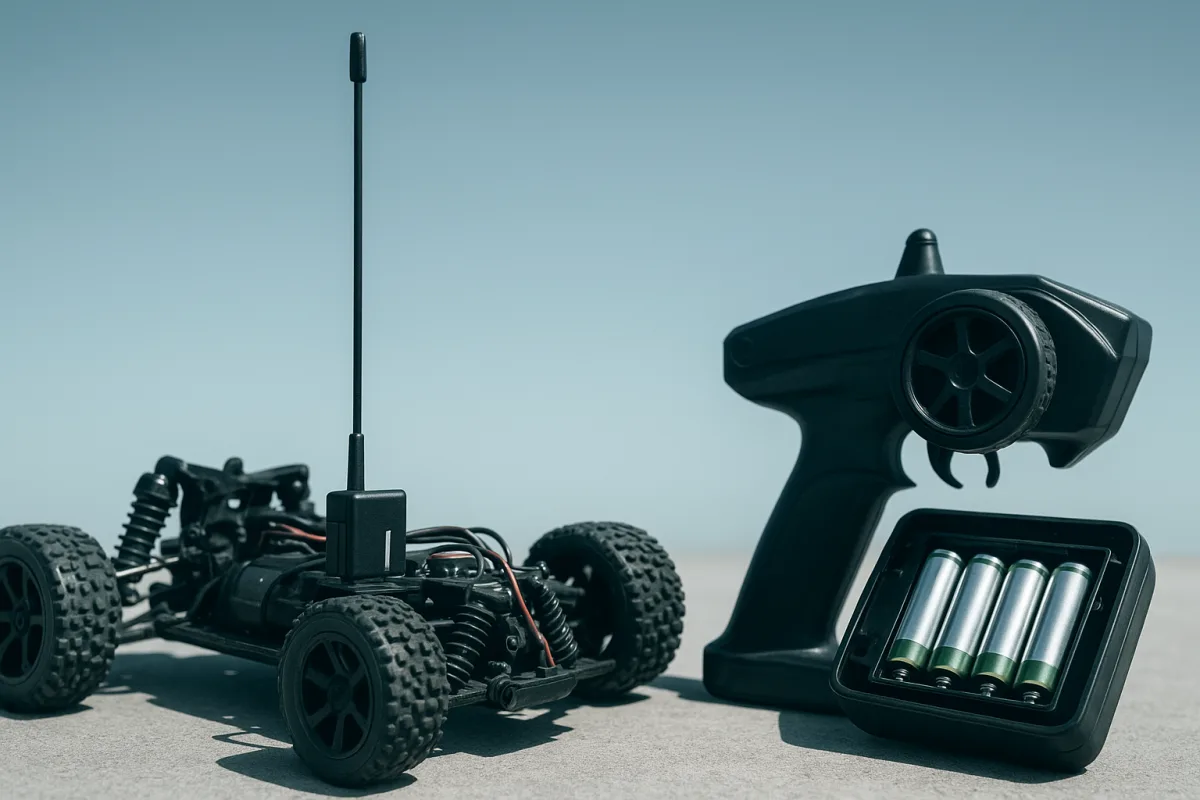
How to Set Up an RC Car Radio for Reliable Communication
Start with the radio system you actually have
Before touching the setup menu, identify whether the car uses a modern 2.4 GHz radio or an older crystal-controlled 27 MHz or 49 MHz system. The setup process, range expectations, and interference risk are very different between them. [5][15]
Most current RC cars use 2.4 GHz equipment. These systems use frequency-hopping spread-spectrum communication, so the transmitter and receiver move between frequencies rather than occupying one fixed channel. That is why several racers can run together without everyone carrying a pile of frequency flags. [4][5]
Older 27 MHz gear has only six channels, while 49 MHz has five. The brief places typical 27 MHz control range around 100 to 300 metres and 49 MHz around 15 to 30 metres, with both systems more vulnerable to interference than 2.4 GHz radios. [5][15]
For a modern 1/10 buggy, SCT, touring car, or 1/8 truggy, a sound 2.4 GHz system should be your baseline. HobbyGradeRC reports that some systems can reach roughly one mile, or 1.6 km, but that is not a realistic promise for every car or location. [4]
Other guidance puts dependable control more commonly around 100 to 500 metres. Terrain, receiver sensitivity, antenna routing, transmitter power, weather, buildings, and local radio noise all shrink that number, so set up for reliable track-side range rather than a headline maximum. [4][8][16]
Power the transmitter before you bind anything
A radio can appear to switch on normally and still be the cause of a bad day. Low transmitter voltage is one of the common causes of glitches, weak control response, and intermittent signal loss. [12][13]
Many transmitters use eight AA cells. Eight alkaline cells produce roughly 12V combined, while eight NiMH rechargeable cells produce roughly 9.6V, because an alkaline AA is nominally 1.5V and a NiMH AA is nominally 1.2V. [11]
That voltage difference matters. Do not assume your transmitter is happy with rechargeables simply because they fit in the tray, and do not assume it can safely charge cells internally. Check the transmitter manual and its battery-label specification first. [11]
Some radios accept dedicated Li-ion or LiFe transmitter packs. Those packs can offer steadier output and longer runtime, but only use a pack intended for that transmitter and its specified voltage range. A radio setup begins with compatible power, not a random battery lead. [11]
For race-day preparation, switch the transmitter on first and look at its voltage display or warning indicator. If the pack is marginal, charge or replace it before binding or range-testing, rather than diagnosing phantom receiver faults later. [12][14]
Bind the receiver using the manufacturer’s sequence
Binding creates the identity link between one transmitter and one receiver. The broad procedure is simple: put the receiver into bind mode, activate bind mode on the transmitter, wait for the LED confirmation, then test steering and throttle. [2][3]
Do not treat that as a universal button sequence. Brands and individual models vary, so use the instructions for your exact transmitter and receiver before swapping plugs, pressing buttons, or cycling power repeatedly. [2][3]
A receiver may enter bind mode through a bind plug, a dedicated button, or a menu-driven process. The transmitter may use its own bind button or a menu item. The confirmation LED is important because it tells you the receiver has completed the link. [2][3]
Traxxas equipment is one example where the details matter. Its procedure uses the transmitter SET button and the receiver LINK button while powering the equipment on, rather than the generic bind-plug method used by some other systems. [3]
Once the LED shows a successful bind, leave the car supported with its wheels clear of the bench. Turn the steering wheel slowly, check left and right direction, then apply throttle gently and confirm brake direction before the car touches the floor. [2][14]
If steering moves backward, correct it with the steering-reverse setting. If throttle or brake direction is wrong, use throttle reverse. Do not solve a reversed channel by physically turning the servo horn or changing motor wiring without first checking the radio settings. [14]
Set endpoints before the servo starts fighting the car
Endpoint adjustment is not glamorous, but it is part of reliable communication because it ensures the receiver’s commands match the actual mechanical travel available. Ignoring endpoints is listed among the common setup mistakes behind radio-control problems. [12]
With steering, turn full left and full right while watching the steering linkage. Reduce each endpoint until the knuckles reach their intended travel without the servo buzzing, binding, or forcing the bellcrank against its stop. [12]
This matters on any scale, but the mechanical consequences differ. A 1/10 buggy servo can be overloaded by a steering rack bound against its stops, while a heavier 1/8 truggy puts even more load into its steering system and power supply.
Set throttle endpoints with the drivetrain unloaded first. Confirm neutral gives a true stop, full throttle reaches full command, and full brake does not create a setting that makes the ESC or mechanical linkage behave unpredictably. [12][14]
Do not use trim to hide a mechanical problem. If the car needs a huge steering trim correction to run straight, inspect the servo horn, steering links, toe setting, and chassis alignment. Radio trim is for small corrections, not compensating for bent parts.
Route the receiver and antenna like they matter
A perfectly bound radio can still lose communication if the receiver is buried in electrical noise. Receiver placement and antenna routing are often more useful places to work than buying a higher-priced radio system. [8][12][13]
Mount the receiver securely where it will not move, and route the antenna vertically outside the body when practical. Keep the antenna away from metal, carbon fiber, motor wiring, and other high-current power leads. [8][12]
Avoid sharp antenna bends. A neatly folded wire tucked beside an ESC, motor, or battery lead may look tidy on the bench, but it is not the routing recommended for stable signal reception. [8][12]
On a 1/10 electric buggy, the receiver often sits close to the ESC, motor wires, and short battery leads, so cable routing deserves attention. On a 1/8 electric truggy, the larger chassis does not remove the issue, because the battery and motor currents are also substantial.
Keep the transmitter antenna fully extended and vertical where your radio uses an external antenna. Do not point it directly at the car as if it were a rifle barrel, and do not wrap your hand around the antenna section. [8]
Also keep the transmitter at sensible distance from the receiver during setup. RCexplained notes that placing a transmitter too close can overload the receiver, producing interference-like symptoms rather than proving that the system has poor range. [10]
Check the car’s receiver power, not just the radio link
A receiver brownout can feel exactly like radio interference. If the receiver loses stable power when steering load rises or throttle is applied, the car may glitch, reset, or stop responding even though the transmitter remains switched on. [12][13]
Start by checking the receiver plug, ESC or receiver-pack connections, and servo leads. A loose connector, damaged wire, or power issue can interrupt communication without any fault in the transmitter’s RF section. [12][13]
Watch for when the problem occurs. A car that glitches only under hard steering input points you toward receiver power or servo load. A car that loses control at distance points more strongly toward antenna routing, obstructions, or environmental interference. [12][13]
A glitch buster capacitor can help in some setups by smoothing receiver voltage dips. Ferrite beads on servo wiring and shielding measures such as aluminum foil are also suggested mitigation tools, but they are not automatic fixes for every car. [8][12][13]
Fit those only after basic wiring, power, binding, and antenna placement are correct. Throwing suppression parts at an improperly routed antenna is like changing 7,000 cSt diff oil to cure a loose wheel nut. Start with the obvious setup fault.
Test range where you will actually drive
Do a control check before every session, especially after moving the receiver, replacing batteries, changing an ESC, or working around the steering system. Keep the vehicle supported initially, then perform a cautious low-speed range check in an open area. [8][12]
Maintain clear line of sight during that check. Buildings, trees, hills, and other obstructions can reduce usable range significantly, even when the radio worked perfectly in an open parking lot or on a clear track straight. [8][16]
Urban areas can be harder on a radio system than an open dirt track. Wi-Fi, Bluetooth, nearby electronics, and broader electromagnetic interference can degrade reception, while rain, snow, and fog can also attenuate radio signals. [1][8][12]
If a problem appears at one venue but not another, do not immediately blame the receiver. Recheck the antenna position, move away from nearby electronics where possible, and compare behavior in a clearer area before spending money on replacement hardware. [1][9][12]
Multiple models can also complicate diagnosis, particularly with older frequency systems. Modern 2.4 GHz radios are designed to coexist better through frequency hopping, but correct binding and sound installation still matter when several drivers are operating nearby. [4][5][9]
Avoid the fixes that skip the actual problem
Increasing transmitter power is sometimes mentioned as a way to gain range, but it may be subject to local radio regulations and is not a sensible first response to a setup issue. There is no substitute for correct binding, healthy batteries, and antenna placement. [8]
Likewise, there is no source-supported radio tune that compensates for a badly routed receiver antenna, a brownout, or a low transmitter pack. The useful order is power, bind status, endpoint setup, receiver placement, then environmental diagnosis. [2][12][13]
No detailed evidence in the research brief supports choosing an RC kit by radio compatibility beyond checking what receiver and transmitter system it includes or accepts. The same applies to motor gearing, LiPo C-rating, shock oil, and diff fluid. Those affect vehicle performance, but they are not established radio-communication fixes here.
When a car stops responding, resist the upgrade reflex. Most of the time, the first wrenching job is not a new transmitter. It is checking the eight AAs, the bind LED, the receiver lead, the antenna tube, and the route past the power wires.
Frequently Asked Questions
How do I bind my RC car transmitter and receiver?
Binding generally involves putting the receiver into bind mode using a bind plug or button, then activating bind mode on the transmitter via a button or menu. Wait for an LED confirmation before testing controls with the wheels off the ground. Procedures vary by brand and model, so always check your manufacturer’s instructions for specifics.
What batteries should I use in my RC car transmitter?
Most transmitters use eight AA cells. Alkaline AA batteries provide about 12V total (1.5V each), while NiMH rechargeable AA cells provide about 9.6V total (1.2V each). Check your transmitter’s manual and battery-label specifications before using rechargeable cells, as not all transmitters support them. Some radios accept dedicated Li-ion or LiFe packs designed for steady output and longer runtime.
How do I route the antenna on an RC car receiver?
Route the receiver antenna vertically and outside the car body if possible. Keep it away from motor wires, carbon fiber, metal parts, and avoid sharp bends to reduce interference and signal loss. Proper antenna placement helps maximize range and signal reliability.
Why does my RC car lose signal or glitch?
Signal loss or glitches are often caused by low transmitter battery voltage, poor antenna placement, incorrect binding, or local radio interference. Before replacing expensive components, check power levels, reposition antennas, and ensure proper binding. Environmental factors like buildings, weather, and nearby electronics can also degrade signal quality.
What is the difference between 2.4 GHz and 27 MHz RC radios?
2.4 GHz radios use frequency-hopping spread-spectrum technology, offering better interference resistance, more channels, and typical reliable ranges of 100 to 500 meters (with some systems reaching up to about 1 mile). Older 27 MHz systems have only six channels, shorter ranges around 100 to 300 meters, and are more susceptible to interference.
How we researched this
This article was assembled from 17 cited references.
Nothing here is based on hands-on testing. Where a figure or finding appears, it belongs to the source cited beside it, and the writing says so rather than implying otherwise. Every source is listed below so you can check it.
Sources
- Characterising and mitigating Bluetooth and WiFi radio frequency interference at the Parkes Observatory
- How To Bind An RC Transmitter And Receiver
- Synchronize your 2.4 GHz radio in 3 minutes
- Do RC Cars Interfere With Each Other? - HobbyGradeRC.com
- What Frequency Do RC Cars Use? - BendTownCars
- FRS Radio Range: Decoding Distance for Outdoor Communication - OneSDR - 🛜 Technology
- How Far Can You Really Communicate Using a CB Radio?
- How to increase the Range of your RC Car – Radio Control Tips
- Radio Systems and How to Avoid Interference • for RC Models
- RC Transmitter Too Close? How It Causes Radio Interference - RCexplained
- Can I use rechargeable AA batteries in my transmitter?
- Why Is My RC Car Glitching or Losing Signal? | RC Setup Lab
- RC Radio Control Problems and Intermittent Signal - RC Plane Lab
- RC Car Won’t Start? Common Causes and Fixes – RaceNRCs
- List of RC frequencies | RC Wiki | Fandom
- Two Way Radios - Understanding Range — Trig Instruments NZ
- RC Model Shop | RC Radio Systems Explained
Related Articles
Troubleshooting RC Car Not Responding: Causes & Fixes
Learn troubleshooting RC car not responding issues with step-by-step fixes for radio, battery, ESC, and receiver problems.
RC Car Electronics Setup
Learn how to set up RC car electronics with proper installation, ESC calibration, wiring layout, and interference reduction for optimal performance.

RC Car Safety Regulations
Learn about RC car safety regulations, radio compliance, and best practices for batteries and equipment in the US, UK, and EU.

Best RC Car for Winter Conditions: Top Picks and Setup Tips
Discover the best RC car for winter conditions with top models, tire advice, battery care, and setup tips for snow and cold weather driving.