
RC Car Electronics Setup
Learn how to set up RC car electronics with proper installation, ESC calibration, wiring layout, and interference reduction for optimal performance.
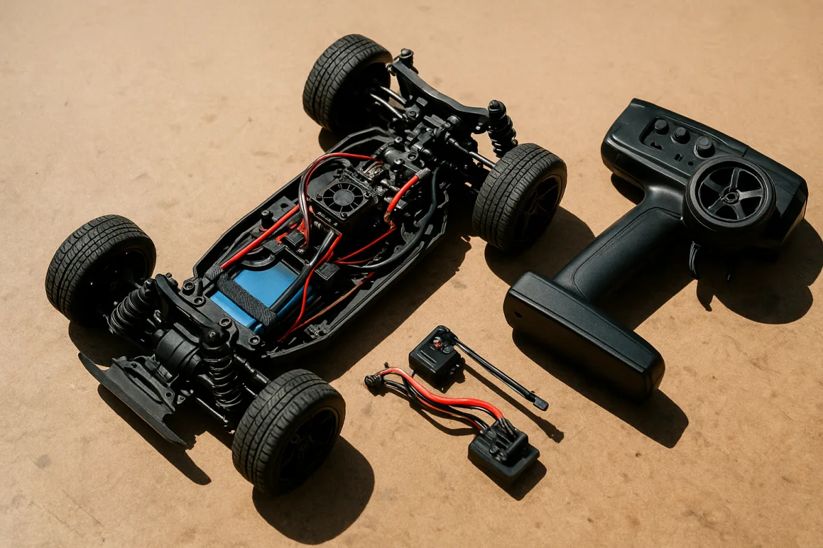
Start with the system on the bench
This guide is for typical 1/10-scale electric cars, including touring cars, stadium trucks, short-course trucks, and 2WD or 4WD buggies. It is not a setup sheet for a 1/8 e-buggy or truggy, where battery voltage, motor load, servo demand, and wiring requirements can be substantially different.
Before installing anything, check that the ESC, motor, battery, receiver, servo, and transmitter are intended to work together. The basic rule is simple: the battery voltage must be inside the ESC’s stated LiPo range, and the battery connector must match the car without a chain of adapters. [7][8]
For 1/10 electric use, a 2S LiPo is 7.4V nominal and remains the normal starting point. A 3S pack is 11.1V nominal and gives a major jump in wheel speed and motor load, so it only belongs in a car whose ESC, motor gearing, drivetrain, and tires can handle it. [6][7]
Do not assume that an ESC marked as suitable for 2S or 3S will tolerate 4S. Some 1/10 ESCs do, but voltage ratings are not universal. Read the actual ESC specification and match it to the exact battery you intend to run, rather than buying by scale label alone.
With the car on a stand, inspect motor bullets, battery connector, receiver plug, and switch lead. Look for bent pins, loose housings, exposed copper, or solder joints that move when the wire is flexed. A bad connection can mimic a bad ESC, bad servo, or radio interference problem.
Install electronics before worrying about setup options
Put the receiver as far as practical from the motor and battery terminals. Those are the noisiest parts of an electric chassis, particularly in a 4WD 1/10 buggy where the receiver box often ends up close to a rear motor and battery saddle. [1]
Run the receiver antenna fully extended and position it high and away from the motor. Do not coil the antenna wire into a tight bundle inside the receiver box just to make the installation look tidy, because range and interference performance matter more than cosmetic cable management. [1]
The steering servo should also be separated from the receiver where the chassis permits. If you must run a servo signal lead longer than six inches, twisting the signal wire with its ground wire can reduce interference pickup. [2]
Start with clean wire routing. Keep motor wires and battery leads together on one side of the chassis where possible, then route receiver and servo leads separately. Crossing is sometimes unavoidable in a compact 1/10 touring car, but avoid running low-voltage receiver wiring parallel to high-current motor wiring for long distances.
If a car glitches only under throttle, inspect layout before buying another receiver. A ferrite bead placed on the servo power lead near the servo case is one listed method for reducing radio-frequency interference, as is a low-ESR capacitor across servo power terminals. [2]
Shielding a servo with grounded copper or aluminum tape is another interference-control option, but it is a problem-solving step rather than a mandatory upgrade. Start with placement, sound connectors, and clean wiring first. Most cars do not need a pile of suppression parts when installed correctly. [2]
Use the connector type fitted to your battery and ESC, rather than mixing standards through adapters. Extra adapters add resistance and can create heat at a point you may not inspect until the plug is already browned or loose. [11]
Be careful with waterproof claims. Waterproof electronics can tolerate wet running better than open electronics, but that does not mean every receiver box, switch, servo case, and connector is safe to submerge. Seal the receiver box properly and inspect its gasket after any wet run. [11]
Center the radio before connecting the servo horn
Turn on the transmitter first and center steering trim, throttle trim, sub-trim, steering dual rate, and any throttle limiting function. Centering controls before power-up gives the ESC and servo a known neutral signal, rather than forcing you to chase an electronic offset later. [3]
Next, power the car with the wheels off the ground. Fit the servo horn as close to 90 degrees to the steering linkage as the spline allows. Then adjust the turnbuckles or steering link mechanically until the front wheels are straight. [3]
This order matters. If the wheels point left with trims centered, correct the linkage first. A steering trim adjustment should make a small correction for track crown or a minor drift, not compensate for a horn installed two splines off or a bent steering link.
Check that the steering moves smoothly from lock to lock with no springy feeling, buzzing, or stalled servo sound. On a 1/10 buggy, the front tires should reach their intended steering travel without the bellcranks hitting chassis features, shocks, or wiring.
Set steering endpoints before the servo starts fighting the car
Set steering EPA or ATV, meaning endpoint adjustment, separately for left and right. Increase each side only until the steering reaches full usable lock, then back it off slightly so the servo is not pushing the linkage against a hard stop. [3]
A servo that buzzes at full steering is not making the car turn harder. It is drawing current, heating itself, and potentially browning out the receiver. That can look like a radio fault, particularly when a high-torque servo is working against oversized tires on a 1/10 short-course truck.
Use steering dual rate after endpoints are correct. Dual rate scales the maximum steering command from the transmitter, allowing a calmer steering response without changing the safe mechanical limits you just set. [4]
For example, full endpoints may be useful for low-speed tight turns, while reduced dual rate can make a high-grip 1/10 4WD buggy less twitchy. That is a driving adjustment, not a substitute for correcting binding, excessive toe-out, poor tire choice, or an over-tight ball differential.
Calibrate the ESC with the drivetrain unloaded
With transmitter trims centered and throttle direction confirmed, follow the ESC’s own calibration procedure. ESC calibration normally records three positions: neutral trigger, full throttle, and full brake or reverse. The button sequence varies by manufacturer, so use the ESC manual for its exact procedure. [3]
Keep the wheels off the ground during this process. At neutral, the motor must remain stopped. At full throttle, it should accelerate cleanly, and at full brake or reverse it should respond only as the ESC’s programmed mode intends.
If the car creeps forward or backward at neutral after calibration, first recheck throttle trim and repeat calibration. Do not use a large trim offset as a permanent fix, because it can reduce available throttle or brake command at one end of trigger travel. [3]
Set throttle dual rate or throttle limiting if the car is too aggressive for its surface or driver. This limits command sent by the transmitter, which can help prevent overpowering a loose 1/10 stadium truck without changing motor timing, gearing, or battery voltage. [4]
Choose the LiPo for the class and the run
LiPo packs are commonly preferred in 1/10 electric cars because they provide high energy density at relatively low weight. For a race-oriented 1/10 buggy or touring car, 4,000 to 6,500mAh is a typical capacity range. [5][6]
For bashing or longer sessions, 5,000 to 8,000mAh is the cited range, assuming the pack physically fits the battery tray. A larger pack can extend runtime, but it also adds weight and may upset balance in a lightweight 2WD buggy. [6][8]
For casual running, 30C to 50C packs are cited as suitable discharge ratings. Racing use calls for 50C or higher, where sustained current demand and voltage sag matter more, especially with a high-grip tire and an aggressive gear ratio. [6]
Do not buy by C-rating alone. Confirm the pack’s dimensions, connector type, and voltage first. A high-C hardcase pack that is too long for the battery tray, or requires an adapter, is not the right pack for the car. [8]
Manage heat instead of trusting the cutoff
ESC thermal protection commonly activates somewhere around 60°C to 74°C, but the exact threshold varies by model. Treat that cutoff as damage prevention, not a sign that the gearing, motor load, or airflow is acceptable. [9]
After a hard run, inspect motor, ESC, battery, connectors, and wires before plugging in another pack. If the connectors are hot, the wiring is soft, or the ESC repeatedly cuts power, stop and find the cause rather than fitting a more expensive motor.
There is no source-backed rule here for changing thermal-cutoff settings based on hot versus cold weather. The practical answer is monitoring: check temperatures regularly, reduce load or gearing if heat climbs, and verify that body shells and receiver-box sealing are not trapping unnecessary heat.
Let LiPos cool after use before charging. Charging a warm pack immediately after a run increases heat stress, while charging below 10°C or 50°F can damage the battery. Bring a cold pack to room temperature before charging. [9]
Budget for the parts that actually solve the fault
Do not start by replacing every electronic component. Correct installation, endpoint setup, calibration, connector condition, and battery compatibility first. Those checks cost little and address the failures most likely to leave a 1/10 electric car dead, glitching, creeping, or overheating.
If a replacement servo is genuinely needed, Horizon Hobby lists the Spektrum S6020 standard digital high-torque servo at about $36. It suits a normal steering replacement where chassis clearance is not tight and the car does not specifically require a low-profile case. [10]
The Spektrum S6245 low-profile high-torque servo is listed around $100 by Horizon Hobby. That format suits chassis layouts with restricted servo height, such as some low-slung 1/10 on-road platforms, but price alone does not make it necessary for every car. [10]
For radio hardware, Horizon Hobby lists the Spektrum SR6100AT six-channel DSMR receiver at about $80, while receiver-and-radio combinations are around $100. Those prices cover electronic components, not batteries, chargers, connectors, installation materials, or replacement parts. [10]
Before the first proper run, perform a range check, confirm steering direction, confirm throttle direction, and verify failsafe behavior with the car on a stand. Then run one pack conservatively, inspect temperatures and connectors, and make one change at a time.
Frequently Asked Questions
How do I properly set up electronics in a 1/10 scale RC car?
Begin by verifying that the ESC, motor, battery, receiver, servo, and transmitter are compatible, especially matching battery voltage to the ESC’s specified LiPo range and connector type. Mechanically set the steering straight before adjusting radio endpoints and trims. Install electronics on the bench first to check connections and avoid issues caused by bent pins or loose wires.
What is the best way to install and route wiring for RC car electronics?
Place the receiver as far as possible from the motor and battery terminals to reduce interference. Extend the receiver antenna fully and position it high and away from the motor without coiling the wire tightly. Keep motor and battery wires grouped on one side of the chassis, and route receiver and servo wires separately, avoiding long parallel runs of low-voltage wiring alongside high-current wires.
How do I calibrate the ESC and center the radio controls on an RC car?
Center the transmitter trims before powering on the ESC. With the wheels off the ground, verify neutral, full throttle, and brake positions according to the ESC’s calibration procedure. Adjust steering endpoints mechanically first, then fine-tune radio trims to prevent servo binding and ensure precise control.
How can I reduce radio interference in my RC car electronics setup?
Keep the receiver, antenna, and servo wiring away from high-current leads and motor terminals. If servo signal wires exceed six inches, twist the signal wire with its ground wire to reduce interference. Additional methods include installing ferrite beads on servo power leads, adding low-ESR capacitors across servo power terminals, or shielding the servo with grounded copper or aluminum tape, though these are typically secondary measures after proper placement and wiring.
What battery voltage should I choose for my RC car electronics?
For 1/10 scale electric RC cars, a 2S LiPo battery (7.4V nominal) is the standard starting point. A 3S LiPo (11.1V nominal) offers higher speed but requires an ESC, motor gearing, drivetrain, and tires capable of handling the increased load. Always confirm that the ESC supports the chosen battery voltage, and do not assume compatibility beyond the ESC’s specified range.
How we researched this
This article was assembled from 11 cited references.
Nothing here is based on hands-on testing. Where a figure or finding appears, it belongs to the source cited beside it, and the writing says so rather than implying otherwise. Every source is listed below so you can check it.
Sources
- Radio Systems and How to Avoid Interference • for RC Models
- Troubleshooting and Fixing RC Car Receiver Range Problems-Micro Servo Motor
- How to Calibrate RC Car Steering for Precise Handling and Better Control -
- RC Car transmitters explained : An overview guide
- RC LIPO Battery
- How to Choose LiPo Batteries for RC Racing | Speed World Raceway
- 2S vs 3S Lipo Batteries for 1/10 Electric RC Cars: Speed, Runtime and ESC Compatibility - Riverhobby Tech (Shenzhen) Co., Ltd.
- Best LiPo Batteries for RC Cars: What to Buy and What to Avoid | MinutesofThunder
- RC LiPo Battery Charging: What the Science Says (Racer's Guide) | So Dialed
- RC Cars & Trucks Surface Radio Servos | Horizon Hobby
- RC Boat Electronics Kit: Wiring Guide From Scratch | RCBoatHQ
Related Articles
Prepare RC Car for Rainy Conditions
Learn how to prepare your RC car for rainy conditions with waterproofing tips, battery safety, tire choice, and post-run maintenance.
How to Set Up RC Car Radio for Reliable Control
Learn how to set up your RC car radio, bind transmitter and receiver, choose batteries, and troubleshoot signal issues for reliable control.
How to Set Up RC Car for Beginners: Complete Starter Guide
Learn how to set up your RC car for beginners with tips on battery, tires, suspension, and motor for a smooth first drive.
How to Adjust RC Car Brakes for Better Control
Learn how to adjust RC car brakes, including ESC calibration, brake strength, brake rate, and drag brake for optimal stopping power and control.